HPEVS AC Electric Motor Drive Systems Wiring
Diagrams, Programming Instructions, and Troubleshooting Information
Header Content Region
Insert text, image or banner ads here, or just delete this text and leave this area blank!


Mining Vehicle Systems
Specialty motors designed and built for your specific applications!
To get information, please click on "Details" tab below.
Specialty motors designed and built for your specific applications!
To get information, please click on "Details" tab below.
Utility Vehicle Systems
We have a drive system to fulfill your utility vehicle requirements!
To get information, please click on "Details" tab below.
We have a drive system to fulfill your utility vehicle requirements!
To get information, please click on "Details" tab below.
Diagnostic and Troubleshooting Documentation.
To obtain this information, please click on "Details" tab below.
To obtain this information, please click on "Details" tab below.


Innovation in Motion, Powered by Electricity


Newsletter Signup
Recent Events

The Recent Events content includes an image that 'AUTO' scales. No need to resize the image, the CSS style sheet will resize the images for you, once rendered in your web page.
To view this page properly in Internet Explorer, it is highly recommended that I.E. Version 9 or higher is used.
- Directions
- On-Road Vehicles
- Golf Car Vehicles
- Hydraulic Pump
- Diagnostic and Controller Fault Codes
- Single Opto Isolator
PLEASE read all documentation prior to installation of your new HPEVS kit into your project.
1. Click on the tab to the right that is related to the project that you are building: On-Road Vehicles, Golf Car Vehicles or even a Hydraulic Pump System.
2. The Diagnostic and Troubleshoot for each system is included within the tabs located right.
3. When the tab has been selected, the tab will turn to a gray background. This signifies that the tab selected is active.
4. Next, select the information of interest.
5. Then click on the cover page to open the pdf file containing the information to view or print.
- Directions
- On-Road Wiring Schematics
- Programming and Diagnostic Instructions
PLEASE read all documentation prior to installation of your new HPEVS kit into your project.
1. Click on either the "On-Road Wiring Schematics" or "Programming Instruction" tabs above to start.
2. When the tab has been selected, the tab will turn to a gray background. This signifies that the tab selected is active.
3. If at any time that you need to contact us directly, please have the Software information available so that we can help you with the issue at hand.
4. This information can be found in numerous spots including the label located on cardboard sleeve that the controller is wrapped in. The cardboard box that the cardboard sleeve containing the controller is located in. This information can also be found if the user is in "Diagnose" mode with the HPEVS system powered up.
For details on how to get to the "Diagnose" mode, please read the programming instructions manual.
5. If you have a Curtis handheld programmer or the Curtis 1314 programming station, the information can be found through either of these options as well.
6. The way to read the software information is from right to left. The first digits prior to the first period is the operating system. The second digits prior to the next period is the build number. The last digits are the application version. Please see below for an example.
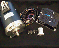
Labels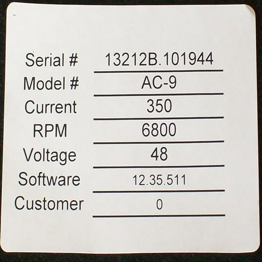 Click on photo for larger view |
Software Information Click on photo for larger view |
- Directions
- Curtis 1232-1238 "e" & "SE" Controller
- Curtis 1232-1238 Controller
- Curtis 1239 Controller
- Motorcycle Generic
1.Download speeds of some files may vary based on your internet connection speed.
2. Click on the RED tabs above to obtain information based on the system that is being used, or if programming instructions are needed, click on that tab. We have included a Generic Motorcycle schematic for those that are using this type of system.
3. Both the single and dual systems are included within the documentation.
4. When the tab has been selected, the tab will turn to a gray background. This signifies that the tab selected is active.
- Software Version 5.30-5.50
|
Curtis 1232/1234/1236/1238 "e" and "SE" Controllers Wiring Schematic 
Click on the above graphic to open PDF file. |
Curtis 1232/1234/1236/1238 "e" and "SE" Controllers Wiring Schematic 
Click on the above graphic to open PDF file. |
|
Curtis 1232/1234/1236/1238 "e" and "SE" Controllers Wiring Schematic  |
Curtis 1232/1234/1236/1238 "e" and "SE" Controllers Wiring Schematic  |
|
On-Road Vehicle Wiring Schematic FOR SOFTWARE VERSIONS UP TO AND INCLUDING GENERIC 318 
Click on the above graphic to open PDF file. |
Curtis 1234-1238 Wiring Schematic FOR SOFTWARE VERSIONS GENERIC 5.00 TO 5.12 
Click on the above graphic to open PDF file. |
|
Curtis 1234-1238 Wiring Schematic FOR SOFTWARE VERSIONS GENERIC 5.13 AND HIGHER 
Click on the above graphic to open PDF file. |
Curtis 1232-1238 Wiring Schematic FOR SOFTWARE VERSIONS GENERIC 5.30 AND HIGHER 
Click on the above graphic to open PDF file. |
Click on the above graphic to open PDF file. |
Click on the above graphic to open PDF file. |
Motorcycle GenericWiring Schematic Click on the above graphic to open PDF file. |
- Directions
- Version 5.0 to 5.09
- Version 5.11 and 5.12
- Version 5.13
- Version 5.14
- Version 5.60
The new generic software package allows for programming of the Curtis Controller.
The motor kit when installed will be drivable, but the following instructions allow for tuning. Some adjustments may be required before operating the vehicle the first time and this manual will guide you through that process.
This new software package will be used with the 1234, 1236, 1238 or 1239 controllers. The new software package also will have integration with the Orion BMS.
The Orion BMS utilizes CAN bus to communicate to the Curtis controller. By following this link, you can view and print the byte structure for the Orion BMS.
Click on the tab to the right "Programming Instruction Ver. 5.0 and up", then click cover page to open the PDF file containing the instructions.
|
Programming Instructions For Software Versions 5.00 to 5.09 
Click on the above graphic to open PDF file. |
|
Programming Instructions
For Software Versions 5.11 and 5.12 
Click on the above graphic to open PDF file. |
|
Programming Instructions
For Software Versions 5.13 
"Updated 3-18-14" Click on the above graphic to open PDF file. |
|
Programming Instructions
For Software Versions 5.14 and Higher  "Updated 3-28-14" Click on the above graphic to open PDF file. |
|
Programming Instructions
For Software Versions 5.60 and Higher 
"Updated 3-22-24" Click on the above graphic to open PDF file. |
- Directions
- Wiring Schematics
- Installation Instructions
- Diagnostic/Troubleshooting
- Accessing Program and Diagnostic Modes via Curtis Display
- Golf Car Throttle Programming
PLEASE read all documentation prior to installation of your new HPEVS kit into your project.
1. To start, click on one of the YELLOW tabs above.
2. Wiring schematics are available.
3. When a tab has been selected, the tab will turn to a gray background. This signifies that the tab selected is active.
4. If at any time that you need to contact us directly, please have the Software information available so that we can help you with the issue at hand.
5. This information can be found in numerous spots including the label located on cardboard sleeve that the controller is wrapped in. The cardboard box that the cardboard sleeve containing the controller is located in. This information can also be found if the user is in "Diagnose" mode with the HPEVS system powered up.
For details on how to get to the "Diagnose" mode, please read the programming instructions manual.
6. If you have a Curtis handheld programmer or the Curtis 1314 programming station, the information can be found through either of these options as well.
7. The way to read the software information is from right to left. The first digits prior to the first period is the operating system. The second digits prior to the next period is the build number. The last digits are the application version. Please see below for an example.
LabelsClick on photo for larger view |
Software InformationClick on photo for larger view |
- Directions
- Club Car
- E-Z-GO
- Tomberlin
- Yamaha
- Generic Schematic
1. To start, click on one of the golf car wiring tabs above based on the golf car that you have. If you are converting a vehicle such as a atv or go-cart, click on the "Generic Schematic".
2. When the tab has been selected, the tab will turn to a gray background. This signifies that the tab selected is active.
3. Then click on the cover page to open the pdf file containing the information needed.
- Standard Motor Schematics
- 2022 Model and ↑ Onward Throttle Wiring
|
Club Car DS Wiring Schematic 
Click on the above graphic to open PDF file. |
Club Car Precedent Wiring Schematic REVISION M 
Click on the above graphic to open PDF file. |
|
2022 and Up Club Car Onward Throttle Wiring and Programming Procedure 
Click on the above graphic to open PDF file. |
|
E-Z-GO Golf Car Wiring Schematic 
Click on the above graphic to open PDF file. |
|
Tomberlin Golf Car Wiring Schematic 
Click on the above graphic to open PDF file. |
|
Yamaha Golf Car Wiring Schematic 
Click on the above graphic to open PDF file. |
|
Generic Wiring Schematic 
Click on the above graphic to open PDF file. |
- Directions
- Club Car
- E-Z-GO
- Yamaha
1. To start, click on one of the instructions tabs above based on the golf car that you have.
2. When the tab has been selected, the tab will turn to a gray background. This signifies that the tab selected is active.
3. Then click on the cover page to open the pdf file containing the information needed.
|
Club Car DS Installation Instructions 
Click on the above graphic to open PDF file |
Club Car Precedent Installation Instructions 
Click on the above graphic to open PDF file. |
|
HPEVS Drive System 
|
Stock Drive System 
|
|
E-Z-GO Golf Car Installation Instructions 
Click on Image to Download |
|
Installation Instructions 
|
with HPEVS Lithium Battery Installation Instructions 
|
|
Yamaha G-19 Golf Car Installation Instructions 
Click on Image to Download |
Yamaha G-Max Golf Car Installation Instructions 
Click on Image to Download |
|
Throttle and Battery Filling Instructions 
Version 800 After March 2007 Click on Image to Download |
Throttle and Parameter Set-up Instructions 
Version 1007 After March 2012 Click on Image to Download |
|
Golf Car Diagnostic Trouble Code Definitions 
Click graphic to open PDF file. |
|
Golf Car Diagnostic Programming and Troubleshooting Guidance  Click graphic to open PDF file. |
|
Golf Car Diagnostic and Troubleshooting Guidance  For "E" Controllers Software Version 1430 and UP Click graphic to open PDF file. |
Golf Car Diagnostic and Troubleshooting Guidance  For NON "E" Controllers Software Version 1426 and UP Click graphic to open PDF file. |
The instruction sets below provides information to the end user on how to access both "Program" mode and "Diagnose" mode using the Fwd/Rev switch, throttle, and menu button. Please select the corresponding document based on the Curtis Instrument motor controller that is utilized.
|
Programming and Diagnostic How-To Instructions For F-Series Motor Controller Software Ver. 1.10 and Up  |
|
Throttle and Battery Filling Instructions
Version 800 After March 2007 Click on Image to Download |
Throttle and Parameter Set-up Instructions
Version 1007 After March 2012 Click on Image to Download |
Software Verison 1.10 and Higher
FOR PROGRAMMING THROTTLE FOR 2022
AND NEWER PRECEDENT ONWARD
PLEASE REFER TO GOLF CAR VEHICLES>WIRING SCHEMATICS>CLUB CAR FOR DOCUMENTATION
 |
- Description
- Hydraulic Pump Schematic
- Diagnostic and Troubleshooting
PLEASE read all documentation prior to installation of your new HPEVS kit into your project.
On the tab labeled "Hydraulic Pump Schematic", you will find a cover page for an electrical schematic for installing our motor system into an hydraulic pump application.
Click on the cover pages to open the PDF file containing the desired schematic.
1. If at any time that you need to contact us directly, please have the Software information available so that we can help you with the issue at hand.
2. This information can be found in numerous spots including the label located on cardboard sleeve that the controller is wrapped in. The cardboard box that the cardboard sleeve containing the controller is located in. This information can also be found if the user is in "Diagnose" mode with the HPEVS system powered up.
For details on how to get to the "Diagnose" mode, please read the programming instructions manual.
3. If you have a Curtis handheld programmer or the Curtis 1314 programming station, the information can be found through either of these options as well.
4. The way to read the software information is from right to left. The first digits prior to the first period is the operating system. The second digits prior to the next period is the build number. The last digits are the application version. Please see below for an example.
LabelsClick on photo for larger view |
Software InformationClick on photo for larger view |
|
Hydraulic Pump Wiring Schematic REVISION E 
Click on the above graphic to open PDF file. |
|
Hydraulic Pump Diagnostic and Troubleshooting Guidance 
Click on the above graphic to open PDF file. |
The attached PDF files below contain information for diagnostic guidance and generic fault codes from Curtis Instruments Controllers. For code faults 51-67, please refer to specific documentation for the type of application that you are working with.
|
Diagnostic Guidance 
Click on the above graphic to open PDF file. |
|
Curtis Instruments Troubleshooting Codes 
Click on the above graphic to open PDF file. |
Curtis Instruments Troubleshooting Codes OS 26 
Click on the above graphic to open PDF file. |
The attached PDF file below contains the schematic for wiring into a system a opto isolator. The purpose of the isolator is to the isolate the digital system signal to drive vehicles gauges such as vehicle tachometer.
|
Single Opto-Isolator Schematic  Click on the above image to open the PDF to view and print |

Copyright 2012-2024. Hi Performance Electric Vehicle Systems. All Rights Reserved.